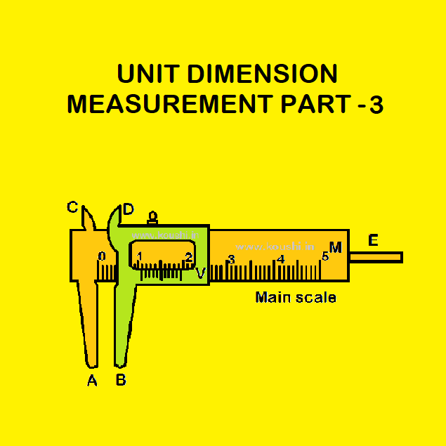
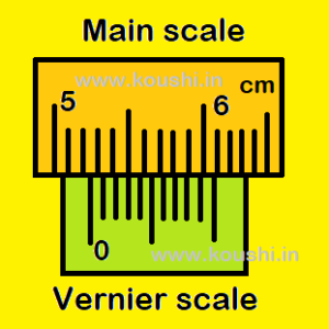
total reading = M + x V.C.
Vernier constant: V.C. = 1 main scale division – 1 vernier scale division
= 1 mm – 0.9 mm = 0.1 mm = 0.01cm.
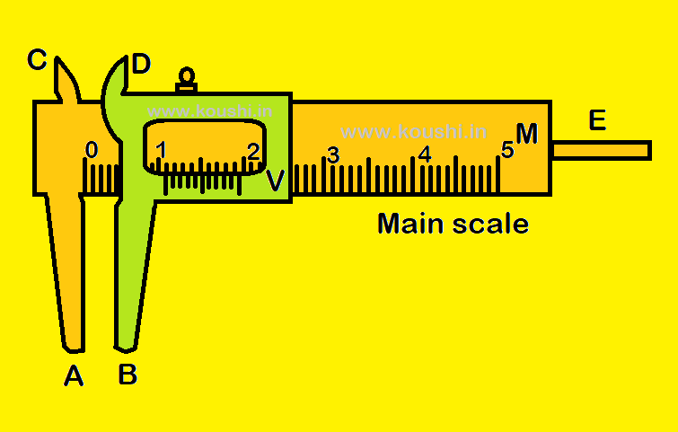
For example, M = 5.2 cm and x = 3
So, total reading = 5.2 + 3  0.01 = 5.23 cm.
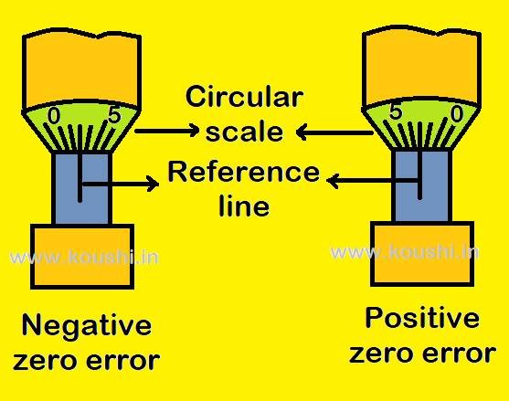
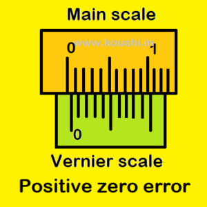
Zero error: If vernier zero does not coincide with zero of main scale when two jaws are connected then there is a zero error. Zero error may be positive or negative.
Zero error is positive if the zero of vernier scale lies to the right of the zero of main scale, when jaws A and B are in contact. The value of positive zero error is subtracted from the total reading.
For example, positive error = 8 0.01 = 0.08 cm and the corrected reading = Total reading – error = 5.22 – 0.08 = 5.14 cm.
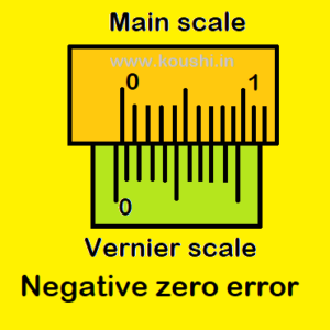
Zero error is negative if the zero of vernier scale lies to the left of the zero of main scale, when jaws A and B are in contact. The value of negative zero error is added with the total reading.
For example, negative error = – 8 0.01 = 0.08 cm and the corrected reading = Total reading – error = 5.22 – (-0.08) = 5.22 + 0.08 = 5.30 cm.
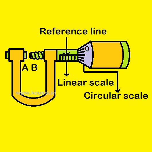
Screw gauge: Screw gauge is used to measure the diameter of a wire or rod. It consists of two scale one is linear and other is circular scale. Each division of linear scale is 1mm if circular scale consists of 100 divisions. If there are 50 divisions in circular scale then each division of linear scale is 0.5mm.
Pitch of the screw =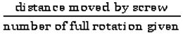
Least count of the screw = ![]()
Calculation of diameter: Calculation for the screw gauge with each linear scale division 1mm and total circular divisions 100.
Pitch of the screw = ![]() = 1mm
= 1mm
Least count of the screw L.C.=  = 0.01mm.
When a rod is inserted in between two screw A and B then the readings of linear scale and circular scale are m and n divisions respectively. Then the reading of diameter = (m + n L.C.) mm.