Capacitance:
If the charge of a conductor is increased then the potential of the conductor is also increased.
Thus, charge (Q)  potential (V) or, Q = CV ——–(1) where C is the capacitance of the conductor and that conductor is called capacitor.
From equation (1) C =  ——-(2) so, the capacitance of the conductor is thus defined as the amount of the charge stored per unit potential difference.
From equation (2), if v = 1 then Q = C. So, the capacitance of the conductor is thus numerically equal to the amount of charge required to increase its unit potential difference.
1 farad (F) =  and 1stat farad =
  .
.
1 farad (F) =  = 9
= 9  1011 stat farad.
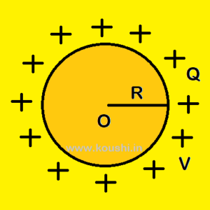
Capacitance of an isolate spherical conductor:
Let us consider a spherical conductor of charge Q and radius r is placed in air (dielectric constant of air is 1).
In C.G.S. system the potential of the conductor is V =  .
.
If C is the capacitance of the conductor, then C = = R.
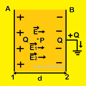
A plate is charged by Q and the outer surface of B is earthed. So –Q charge is induced in the inner surface of B. If σ is the surface charge density of each plate then the electric field between the plates is  =
=  +
+  =
=  + =
+ =  (where and are the field intensity of plate A and B respectively).
If V is the potential difference between the plates then, V = E.d =  .
.
The capacitance of the parallel plate capacitor C = =  =
=  .
.
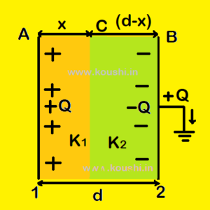
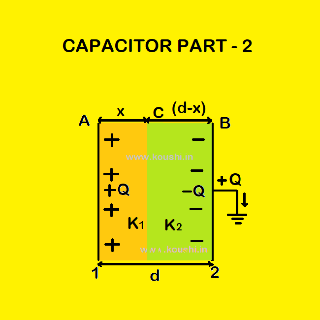
The electric field between AC and CB are respectively E1 =  =
= 
and E2 =  =
=  (where σ is the surface charge density of each plate).
The potential difference between AC is VA – VC = E1.x = 
And the potential difference between CB is VC – VB = E2(d-x) = 
If V is the potential difference between the plates then, V = (VA – VC) + ( VC – VB)
Or, V = 
Or, V = 
The capacitance of the parallel plate capacitor C = =  .
.